


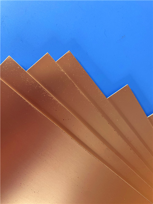

RT/duroid® εναλλακτικό υλικό; TLY-5 DK2.2 Laminate PCB
Υπεύθυνος : Sally Mao
Τηλεφωνικό νούμερο : 86-755-27374847
Το WhatsApp : +8618277967574
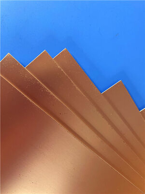
| Μάρκα: | Taconic | Αριθμό μοντέλου: | TLX-8 |
|---|
Περιγραφή προϊόντων
Είναι ένα υπόστρωμα μικροκυμάτων PTFE υψηλού όγκου, ενισχυμένο με υαλοΐνες, κατασκευασμένο από την AGC. Έχει διηλεκτρική σταθερά (Dk) 2,55 ±0,04 στα 10 GHz. Ο συντελεστής απωλειών (Df) είναι 0,0018 στα 10 GHz. Προσφέρει εξαιρετική απόδοση PIM (μετρημένη σε λιγότερο από -160 dBc). Το υλικό είναι σταθερό ως προς τις διαστάσεις. Έχει πολύ χαμηλή απορρόφηση υγρασίας (0,02%). Έχει βαθμολογία UL94 V-0. Είναι κατάλληλο για σχεδιασμούς μικροκυμάτων με χαμηλό αριθμό στρώσεων. Είναι ιδανικό για εφαρμογές που απαιτούν μηχανική ενίσχυση σε αυστηρά περιβάλλοντα, συμπεριλαμβανομένων των διαστημικών, αεροδιαστημικών και αμυντικών εφαρμογών.
Τι PCB μπορεί να κατασκευαστεί με αυτό;
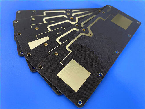
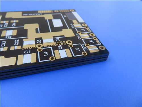
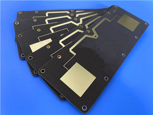
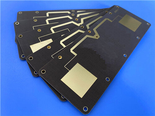
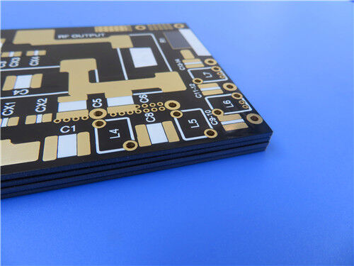
Μπορεί να παρασχεθεί μια ολοκληρωμένη λύση RF PCB 2 στρώσεων. Η πλακέτα βασίζεται στο υλικό TLX-8. Το τελικό πάχος είναι 0,85 mm. Το βάρος του χαλκού είναι 1 oz ανά στρώση. Εφαρμόζεται επιχρύσωση καθαρού χρυσού ως φινίρισμα επιφάνειας. Δεν εφαρμόζεται συγκολλητική μάσκα σε καμία πλευρά. Λευκή μεταξοτυπία εκτυπώνεται στην επάνω στρώση. Η ελάχιστη γραμμή και απόσταση είναι 5 και 7 mils. Το ελάχιστο μέγεθος οπής είναι 0,3 mm. Το πάχος της επιχρύσωσης των vias είναι 20 μm. Το πρότυπο ποιότητας είναι IPC Class 2. Αυτή η πλακέτα είναι ιδανική για κεραίες, συστήματα ραντάρ, κινητές επικοινωνίες και εξοπλισμό δοκιμών μικροκυμάτων.
1. Επισκόπηση Υλικού
Το TLX-8 είναι ένα laminate PTFE υαλοΐνας. Κατασκευάζεται από την AGC (πρώην Taconic). Είναι ένα υλικό κεραίας υψηλού όγκου. Προσφέρει αξιοπιστία σε ένα ευρύ φάσμα εφαρμογών RF. Το υλικό είναι ευέλικτο. Είναι διαθέσιμο σε ένα ευρύ φάσμα πάχους και επιλογών επικάλυψης χαλκού. Είναι κατάλληλο για σχεδιασμούς μικροκυμάτων με χαμηλό αριθμό στρώσεων.
Το υλικό προσφέρει μηχανική ενίσχυση. Αυτό είναι σημαντικό όπου ένα υπόστρωμα εκτίθεται σε αυστηρά περιβάλλοντα.
Παραδείγματα περιλαμβάνουν:
Αντοχή στην ερπυσμό για PCB που βιδώνονται σε περίβλημα που αντιμετωπίζει υψηλά επίπεδα δονήσεων κατά την εκτόξευση στο διάστημα
Έκθεση σε υψηλές θερμοκρασίες σε μονάδες κινητήρων
Αντοχή στην ακτινοβολία στο διάστημα (καταχωρημένο από τη NASA για χαμηλή εκπομπή αερίων)
Αντοχή σε ακραία περιβάλλοντα στη θάλασσα για κεραίες πολεμικών πλοίων
Αντοχή σε ευρύ φάσμα θερμοκρασιών για υποστρώματα υψομέτρου κατά την πτήση
Το TLX-8 έχει μακρά ιστορία στο διάστημα. Χρησιμοποιείται όπου απαιτείται ενίσχυση από υαλοΐνες υφασμένες.
Βασικά Χαρακτηριστικά του TLX-8:
Laminate PTFE Υαλοΐνας — Το υλικό συνδυάζει PTFE με ενίσχυση από υφασμένες υαλοΐνες. Αυτό παρέχει εξαιρετική μηχανική αντοχή και σταθερότητα διαστάσεων.
Χαμηλό και Σταθερό Dk — Το Dk είναι 2,55 ±0,04 στα 10 GHz. Η διακύμανση του Dk είναι περίπου ±2% από -55°C έως 125°C.
Χαμηλός Συντελεστής Απωλειών — Το Df είναι 0,0018 στα 10 GHz. Η απώλεια σήματος ελαχιστοποιείται.
Εξαιρετική Απόδοση PIM — Το PIM μετράται σε λιγότερο από -160 dBc. Αυτό είναι κρίσιμο για κεραίες σταθμών βάσης και συστήματα RF χαμηλής παραμόρφωσης.
Εξαιρετική Θερμική Σταθερότητα — Η θερμοκρασία αποσύνθεσης (Td) είναι 535°C (2% απώλεια βάρους). Η Td είναι 553°C (5% απώλεια βάρους).
Σταθερότητα Διαστάσεων — Το υλικό είναι σταθερό ως προς τις διαστάσεις. Μετά από ψήσιμο, το MD είναι 0,06 mm/m και το CD είναι 0,08 mm/m.
Χαμηλή Εκπομπή Αερίων — Το υλικό είναι καταχωρημένο από τη NASA για χαμηλή εκπομπή αερίων. TML είναι 0,03%. CVCM είναι 0,00%. WVR είναι 0,01%.
Χαμηλή Απορρόφηση Υγρασίας — Η απορρόφηση υγρασίας είναι μόλις 0,02%. Διασφαλίζεται σταθερή απόδοση σε υγρά περιβάλλοντα.
2. Φύλλο Τεχνικών Δεδομένων TLX-8
| Ιδιότητα | Τυπική Τιμή | Μονάδες | Συνθήκη | Μέθοδος Δοκιμής |
| Διηλεκτρική Σταθερά | 2,55 ±0,04 | — | @ 10 GHz | IPC-650 2.5.5.3 |
| Συντελεστής Απωλειών | 0,0018 | — | @ 10 GHz | IPC-650 2.5.5.5.1 |
| Απόδοση PIM | < -160 | dBc | 20 W ανά κανάλι @ 800/1800 MHz | Μέτρηση κουπονιού PCB |
| Εκπομπή Αερίων (TML) | 0,03 | % | 4 H 257°F @ ≤5×10⁻⁵ Torr | ASTM E 595 |
| Εκπομπή Αερίων (CVCM) | 0 | % | 4 H 257°F @ ≤5×10⁻⁵ Torr | ASTM E 595 |
| Εκπομπή Αερίων (WVR) | 0,01 | % | 4 H 257°F @ ≤5×10⁻⁵ Torr | ASTM E 595 |
| Αντίσταση Επιφάνειας (Αυξημένη Θερμοκρασία) | 6,605 × 10⁸ | Mohm | — | IPC-650 2.5.17.1 Sec. 5.2.1 |
| Αντίσταση Επιφάνειας (Συνθήκη Υγρασίας) | 3,550 × 10⁶ | Mohm | — | IPC-650 2.5.17.1 Sec. 5.2.1 |
| Αντίσταση Όγκου (Αυξημένη Θερμοκρασία) | 1,110 × 10¹⁰ | Mohm/cm | — | IPC-650 2.5.17.1 Sec. 5.2.1 |
| Αντίσταση Όγκου (Συνθήκη Υγρασίας) | 1,046 × 10¹⁰ | Mohm/cm | — | IPC-650 2.5.17.1 Sec. 5.2.1 |
| Σταθερότητα Διαστάσεων (MD – Μετά από Ψήσιμο) | 0,06 | mm/m | — | IPC-650 2.4.39 Sec. 5.4 |
| Σταθερότητα Διαστάσεων (CD – Μετά από Ψήσιμο) | 0,08 | mm/m | — | IPC-650 2.4.39 Sec. 5.4 |
| Σταθερότητα Διαστάσεων (MD – Θερμική Καταπόνηση) | 0,09 | mm/m | — | IPC-650 2.4.39 Sec. 5.5 |
| Σταθερότητα Διαστάσεων (CD – Θερμική Καταπόνηση) | 0,1 | mm/m | — | IPC-650 2.4.39 Sec. 5.5 |
| Θερμική Αγωγιμότητα | 0,19 | W/m·K | — | ASTM F433 / ASTM 1530-06 |
| CTE Άξονας X | 21 | ppm/°C | 25-260°C | IPC-650 2.4.41 / ASTM D 3386 |
| CTE Άξονας Y | 23 | ppm/°C | 25-260°C | IPC-650 2.4.41 / ASTM D 3386 |
| CTE Άξονας Z | 215 | ppm/°C | 25-260°C | IPC-650 2.4.41 / ASTM D 3386 |
| Td (2% Απώλεια Βάρους) | 535 | °C | — | IPC-650 2.4.24.6 (TGA) |
| Td (5% Απώλεια Βάρους) | 553 | °C | — | IPC-650 2.4.24.6 (TGA) |
| Αντοχή Ξεφλουδίσματος (1 oz ED) | 2,63 (15) | N/mm (lbs/in) | Θερμική καταπόνηση | IPC-650 2.4.8 Sec. 5.2.2 |
| Αντοχή Ξεφλουδίσματος (1 oz RTF) | 2,98 (17) | N/mm² (kpsi) | — | IPC-650 2.4.8 Sec. 5.2.2 |
| Αντοχή Ξεφλουδίσματος (½ oz ED) | 2,45 (14) | N/mm² (kpsi) | Αυξημένη θερμοκρασία. | IPC-650 2.4.8.3 |
| Μέτρο Young (MD) | 6.757 (980) | N/mm² (psi) | — | ASTM D 902 |
| Μέτρο Young (CD) | 8.274 (1.200) | N/mm² (psi) | — | ASTM D 902 |
| Απορρόφηση Υγρασίας | 0,02 | % | — | IPC-650 2.6.2.1 |
| Διηλεκτρική Αντοχή | >45 | kV | — | IPC-650 2.5.6 |
| Βαθμολογία Ευφλεκτότητας | V-0 | — | — | UL-94 |
3. Βασικά Πλεονεκτήματα του TLX-8
|
Χαρακτηριστικό |
Όφελος |
|
Το Dk είναι 2,55 ±0,04 |
Η στενή ανοχή επιτρέπει σταθερό έλεγχο σύνθετης αντίστασης |
|
Το Df είναι 0,0018 στα 10 GHz |
Οι χαμηλές απώλειες ελαχιστοποιούν την εξασθένηση σήματος σε κυκλώματα μικροκυμάτων |
|
Το PIM είναι< -160 dBc |
Εξαιρετική απόδοση χαμηλής παραμόρφωσης για κεραίες σταθμών βάσης |
|
Το Td είναι > 535°C |
Παρέχεται εξαιρετική αντοχή στη θερμική αποσύνθεση |
|
Το CTE X/Y είναι 21/23 ppm/°C |
Επιτυγχάνεται καλή σταθερότητα διαστάσεων |
|
Χαμηλή εκπομπή αερίων (TML 0,03%) |
Καταχωρημένο από τη NASA για διαστημικές εφαρμογές |
|
Η απορρόφηση υγρασίας είναι 0,02% |
Η πολύ χαμηλή απορρόφηση νερού διασφαλίζει σταθερή απόδοση σε υγρά περιβάλλοντα |
|
Επιτυγχάνεται βαθμολογία UL94 V-0 |
Διασφαλίζεται η συμμόρφωση με την ασφάλεια πυρός |
|
Ευρύ φάσμα πάχους (0,064-6,35 mm) |
Ενεργοποιείται η ευελιξία σχεδιασμού |
|
Υποστηρίζεται παραγωγή υψηλού όγκου |
Οικονομικά αποδοτικό υλικό κεραίας |
4. Πεδία Εφαρμογής
Το TLX-8 χρησιμοποιείται σε πολλές απαιτητικές εφαρμογές RF και μικροκυμάτων:
- συστήματα ραντάρ
- κινητές επικοινωνίες
- εξοπλισμός δοκιμών μικροκυμάτων
- συσκευές μετάδοσης μικροκυμάτων
- ζεύκτες, διαχωριστές, συνδυαστές, ενισχυτές, κεραίες
5. Προσαρμοσμένο RF PCB 2 Στρώσεων – Πλήρης Προδιαγραφή
Μπορεί να παρασχεθεί μια ολοκληρωμένη λύση RF PCB 2 στρώσεων βασισμένη στο TLX-8. Οι προδιαγραφές εμφανίζονται παρακάτω.
Προδιαγραφές Πλακέτας
| Προδιαγραφή | Λεπτομέρεια |
| Τύπος Πλακέτας | RF PCB 2 Στρώσεων |
| Βασικό Υλικό | TLX-8 (πυρήνας 0,762 mm / 30 mil) |
| Τελικό Πάχος Πλακέτας | 0,85 mm |
| Τελικό Βάρος Χαλκού | 1 oz (35 μm) ανά στρώση |
| Διαστάσεις Πλακέτας | 76,4 × 98,6 mm (1 τεμάχιο) |
| Ανοχή Διαστάσεων | ±0,15 mm |
| Ελάχιστη Γραμμή / Απόσταση | 5 / 7 mils |
| Ελάχιστο Μέγεθος Οπής | 0,3 mm |
| Πάχος Επιχρύσωσης Via | 20 μm |
| Φινίρισμα Επιφάνειας | Επιχρύσωση Καθαρού Χρυσού |
| Μάσκα Συγκόλλησης Επάνω | Όχι |
| Μάσκα Συγκόλλησης Κάτω | Όχι |
| Μεταξοτυπία Επάνω | Λευκή |
| Μεταξοτυπία Κάτω | Όχι |
| Ταξινόμηση IPC | Κλάση 2 |
| Μορφή Σχεδίου | Gerber RS-274-X |
| Δοκιμές | 100% Ηλεκτρική Δοκιμή (πριν την αποστολή) |
| Διαθεσιμότητα | Παγκόσμια |
6. Γιατί Χρησιμοποιείται το Φινίρισμα Καθαρού Χρυσού
Επιλέγεται επιχρύσωση καθαρού χρυσού για αυτό το RF PCB. Τα πλεονεκτήματα παρατίθενται παρακάτω.
| Πλεονέκτημα | Όφελος |
| Παρέχεται εξαιρετική συγκολλησιμότητα | Διατίθεται επιφάνεια χωρίς οξείδωση για την προσάρτηση εξαρτημάτων |
| Υποστηρίζεται συγκόλληση με σύρμα | Μπορούν να χρησιμοποιηθούν εξαρτήματα RF που απαιτούν συγκόλληση με χρυσό σύρμα |
| Παρέχεται αντοχή στη διάβρωση | Οι χάλκινες γραμμές προστατεύονται σε αυστηρά περιβάλλοντα |
| Επιτυγχάνεται χαμηλή αντίσταση επαφής | Αυτό είναι κατάλληλο για ακροδέκτες σύνδεσης και σημεία δοκιμής |
| Διατηρείται μεγάλη διάρκεια ζωής στο ράφι | Η συγκολλησιμότητα διατηρείται για εκτεταμένες περιόδους |
7. Γιατί Δεν Χρησιμοποιείται Μάσκα Συγκόλλησης
| Πλεονέκτημα | Όφελος |
| Μειώνεται το βάρος | Επιτυγχάνονται λεπτές, ελαφριές πλακέτες |
| Μειώνεται το κόστος | Εξαλείφεται η εφαρμογή μάσκας συγκόλλησης |
| Βελτιστοποιείται η απόδοση RF | Η μάσκα συγκόλλησης μπορεί να επηρεάσει τη σύνθετη αντίσταση και να εισάγει απώλειες σε υψηλές συχνότητες |
| Ενεργοποιείται η γείωση με γυμνό χαλκό | Μπορούν να γίνουν απευθείας συνδέσεις γείωσης |
| Απλοποιείται η οπτική επιθεώρηση | Οι γραμμές και τα pads είναι ευδιάκριτα |
Ε1: Ποια είναι η διηλεκτρική σταθερά του TLX-8;
Η διηλεκτρική σταθερά διεργασίας είναι 2,55 ±0,04 στα 10 GHz. Η διακύμανση του Dk είναι περίπου ±2% από -55°C έως 125°C. Αυτό το σταθερό Dk επιτρέπει σταθερό έλεγχο σύνθετης αντίστασης.
Ε2: Ποια είναι η απόδοση PIM του TLX-8;
Το PIM μετράται σε λιγότερο από -160 dBc. Αυτή η μέτρηση πραγματοποιείται χρησιμοποιώντας ένα κατασκευασμένο κουπόνι PCB. Η δοκιμή χρησιμοποιεί 20 watt ανά κανάλι στα 800 και 1800 MHz. Αυτή η εξαιρετική απόδοση PIM καθιστά το TLX-8 ιδανικό για κεραίες σταθμών βάσης.
Ε3: Είναι το TLX-8 κατάλληλο για διαστημικές εφαρμογές;
Ναι. Το TLX-8 έχει μακρά ιστορία στο διάστημα. Είναι καταχωρημένο από τη NASA για χαμηλή εκπομπή αερίων. Οι τιμές εκπομπής αερίων είναι TML 0,03%, CVCM 0,00% και WVR 0,01%. Χρησιμοποιείται σε διαστημικά οχήματα εκτόξευσης, δορυφόρους και άλλες διαστημικές εφαρμογές.
Ε4: Τι πάχη είναι διαθέσιμα για το TLX-8;
Το TLX-8 είναι διαθέσιμο σε πάχη από 0,064 mm (0,0025") έως 6,35 mm (0,250"). Μπορεί να κατασκευαστεί σε προσαυξήσεις 0,005" (0,125 mm). Τα τυπικά μεγέθη πάνελ περιλαμβάνουν 18" × 24" (457 mm × 610 mm) και άλλα μεγέθη έως 36" × 48".
Ε5: Πού μπορεί να ληφθεί το επίσημο φύλλο δεδομένων TLX-8;
Το επίσημο φύλλο δεδομένων είναι διαθέσιμο από την AGC (πρώην Taconic). Το email επικοινωνίας είναι agc-ml.info-maltimaterial@agc.com. Η ομάδα μας μπορεί επίσης να παρέχει τεκμηρίωση.
Έτοιμοι να Ξεκινήσετε;
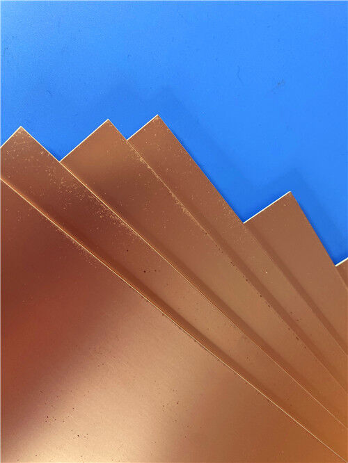
Μπορεί να παρασχεθεί ακατέργαστο laminate TLX-8. Μπορούν να κατασκευαστούν πλήρως κατασκευασμένα RF PCB 2 στρώσεων με φινίρισμα καθαρού χρυσού και δυνατότητα λεπτών γραμμών.
Επικοινωνήστε μαζί μας σήμερα για:
Δειγματοληψία και δοκιμή υλικού
Βοήθεια σχεδιασμού κυκλωμάτων RF
Υποστήριξη υπολογισμού σύνθετης αντίστασης και σχεδιασμού
Προσφορά PCB και έλεγχος DFM
Τεχνική υποστήριξη για τη συγκεκριμένη εφαρμογή σας
Εισάγετε το μήνυμά σας

RO4350B, 4003C Rogers 5880, 5870, 6002, 6010, 6006, 6035 RO3003, RO3035, RO3006, RO3010, RO3210, RO3203
TLX-8, TLX-6, TLX-9, TLX-0, TLX-7, TLY-3, TLY-5, RF-35TC, RF-60TC, RF-35A2, RF-60A, AD450, AD600, TMM4, TC350
| Shenzhen Bicheng Electronics Technology Co., Ltd |
| κωμόπολη 6-11C Shidai Jingyuan Fuyong, περιοχή Baoan, πόλη Shenzhen, επαρχία Γκουαγκντόνγκ, Κίνα |
| 86-755-27374946 |
| sales30@bichengpcb.com |